What is a Transformer Polarity test?
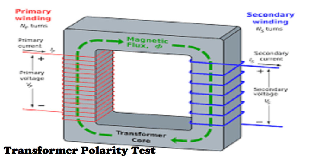
For the purpose of moving electrical energy from one alternating current circuit to one or more circuits, an electromechanical device known as a transformer steps up or steps down the voltage. The idea of electrical polarity comes from the behavior of current flowing from high voltage point to low voltage due to potential differences between them.
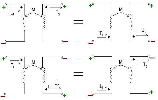
It defines the direction of current flow in transformers. The induced voltage between HV and LV windings of the transformer is said to be polarized in either one direction or other. In the case of electrical repair, a polarity test is done to confirm the precise line connection and neutral conductors. In AC transformers.
This article will highlight the necessary information and step-by-step guidelines to its readers about performing a transformer polarity test, the types of polarity, and the benefits of performing a polarity test.
How to perform a transformer polarity test?

The polarity test verifies that just the phase conductor serves as the only connection for all single-pole devices, including switches, circuit breakers, and fuses. Because electricians occasionally connect things incorrectly, we cannot trust them.
When checking the transformer’s polarity, there are typically four distinct scenarios that can occur:
- The phase conductor is the only connection for all single-pole equipment.
- Connection to this conductor should be done via the lamp holder’s center terminal.
- Every socket channel’s polarity must confirm whether it is radial or ring.
- A tester of standard voltage must correct the central supply polarity.
Verify the transformer’s polarity by exciting the primary winding using a low voltage source. Jump the transformer’s H1 terminal to the X1 terminal first. The H2 and X2 terminals should now be connected to a voltmeter. Apply a lower voltage across H1 and H2, then note the voltage that is displayed on the meter. If the value in a transformer equals the total of the high and low windings, additive polarity is said to exist. If the meter reads more than the voltage supplied, the polarity is otherwise subtractive.
Types of transformer polarity
Additive and subtractive polarities are the two types of transformer polarities that are commercially offered. To find out which type of polarity transformer winding has, we have to connect one terminal of the transformer with a primary winding and one with secondary winding and connect the remaining terminals with a voltmeter.
1. Addictive polarity
Additive polarity is used in small-scale distribution transformers. In this type of polarity, the transformer’s primary and secondary coil voltages will be added to generate the transformer’s overall voltage.
The secondary and primary voltages are added up and measured by the voltmeter. VC stands for the voltmeter reading. Additionally, VA and VB are used to indicate the major and secondary voltages, respectively. In additive polarity, the voltmeter follows the following equation;
VC = VA + VB
2. Subtractive polarity
Subtractive polarity is used in large-scale distribution transformers. In this kind of polarity, the voltage between the primary and secondary coils of the transformer will be equal to the sum of the two voltages. VC denotes the voltmeter reading, and the equation of the voltmeter reading is;
VC = VA – VB
In the case of a step-down transformer, the equation will become Vc = Va – Vb. If it is Vc = Vb – Va, it will be a step-up transformer.
Steps to perform a transformer polarity test

Following are the steps to perform the polarity of a transformer in detail.
- As indicated in the circuit schematic above, assemble the circuit and place the autotransformer in the zero position.
- Turn on the single-phase power source.
- Note the voltages VA, VB, and VC displayed by the voltmeter.
- The transformer has additive polarity if the reading of the VC indicates that the values of VA and VB have added, its equation is VC = VA+VA
- The transformer is referred to as having a subtractive or negative polarity connection if the measurements for VA and VB must be subtracted in order to obtain the measurement for VC.
One must be careful to ensure that the maximum measurement value of the voltmeter’s voltage, Vc, is greater than the addition of Va (the primary winding) and Vb (the secondary winding), lest the sum of Va and Vb come into contact with it during the additive polarity.
When the subtractive polarity is needed but already has it, we may easily switch to additive polarity by keeping one of the primary or secondary windings in place and switching the winding connected to the other one. If we had additive polarity but needed subtractive polarity, we can take a similar step as above.
Do you want to know helpful facts about Tile Grouts? Read this amazing article in our Home Improvement category: Each And Everything You Need To know About How Long For Grout To Dry?
Benefits of performing transformers polarity tests
The main advantage of conducting polarity tests is that we can operate the transformers in parallel without having any short circuits by understanding the polarity of various windings.
Transformer polarity is beneficial for connecting numerous single-phase transformers to create a three-phase bank or paralleling transformers for increased capacity.
To function to meet peak demands, the transformers are connected in parallel. It is necessary to understand the primary and secondary transformer windings for the transformer to operate in parallel.
The other transformer’s primary winding should be linked to its primary winding’s positive terminal. One can perform the same process for secondary windings with the same polarity terminals.
Suppose the primary winding of the other transformer’s positive primary winding is connected to its negative primary winding negative terminal. The entire device is then damaged due to the short winding circuit. Therefore, a polarity test is performed on the transformer for appropriate parallel functioning.
Methods of transformer polarity test
The following are some of the several polarity testing techniques that can be used.
- Polarity Testing through Visual Inspection
A visual check-up can be used to confirm the precise execution of wires connecting to core colors. Throughout the positioning process, polarity must always be checked visually, especially when testing is impossible to use as verification.
- Polarity through Continuity Testing
If the testing method explained above is impossible, you must conduct this test using an ohmmeter with low resistance. While a person isn’t continuously checking the radial and ring final circuits, some techniques require checking and physically inspecting the polarity of the socket’s permanent devices and outlets.
- Live Testing of Polarity
Suppose the above two approaches cannot be used for some reason. In that case, we can perform live polarity testing using the typical GS38 voltage. For the live testing, we follow the following steps
- Verify the LINE terminal and the NEUTRAL terminal.
- Check the LINE terminal and the EARTH terminal for errors.
- Check the EARTH terminal as well as the NEUTRAL terminal.
The total voltage between the line neutral conductor and the line earth conductor must be specified by the test device. In between Earth and Neutral, there is no voltage.
Final Words
Performing a transformer polarity test is no doubt a good practice as it is done to prevent transformers connected in parallel from short circuits and other hazards. It’s critical to properly understand the type of transformer to select the one suiting your needs. No matter the current transformer type, perform the polarity test using one of the above three methods. This article provides detailed knowledge about how anyone can perform a Polarity test in transformers.
Apart from this, if you are interested to know more about Breaker Tripped then visit our TECH category.
Frequently Asked Questions (FAQs)
- Why is it essential to perform the polarity test of a transformer?
We verify the polarity of parallel transformers to ensure that we are connecting windings with the same polarity and not those with the opposite polarity.
- How do you determine the polarity of an instrument transformer?
Start by applying a low voltage of about 120 volts to the primary terminals. On the secondary terminals, this will produce a voltage of 12 volts with a 10:1 turn ratio. If the voltmeter displays the sum, the polarity is additive.


